December 10th, 2011
You wanted a big update, well here it is! After going back to the drawing board and sketching out plan after plan, I finally settled on the benchwork plan I had already started. It was the best setup I could come up with, with regards to town placement, main line placement and isle widths. It's not perfect, but the positives outweigh the negatives. I'm hoping this plan is even better than the last layout plan of OVSv3. Speaking of that, I did think of just going with the same layout benchwork setup as last time. But in my quest to always try to make things better, I decided against it. Besides, I had already spent 3 years building that one and wanted to try something new. Things happen for a reason, and losing the last layout maybe was the world's way of saying "nope, you can do better". Time will tell!
Ok, the issue I was having last update was the placement of the upper level trackage coming out of the hole in the wall from staging. Here is what I was trying to achieve. I wanted the upper level main line to go around the helix instead of just curving around and going through the new backdrop (where the "24" and "22" are)
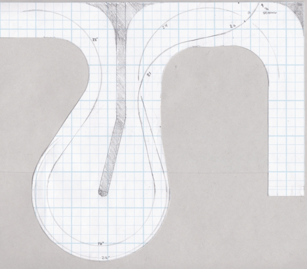
To gain this, I would have to drop the helix down one full turn and lose the visability of that last curve on the helix, one thing I really didn't want to do. If I did, then you wouldn't see your train until it came around to the right of the above picture, after passing under the tracks going to staging.
Now if I could get away with some strategically placed tunnels, then maybe I could make that last curve of the helix visible. . .
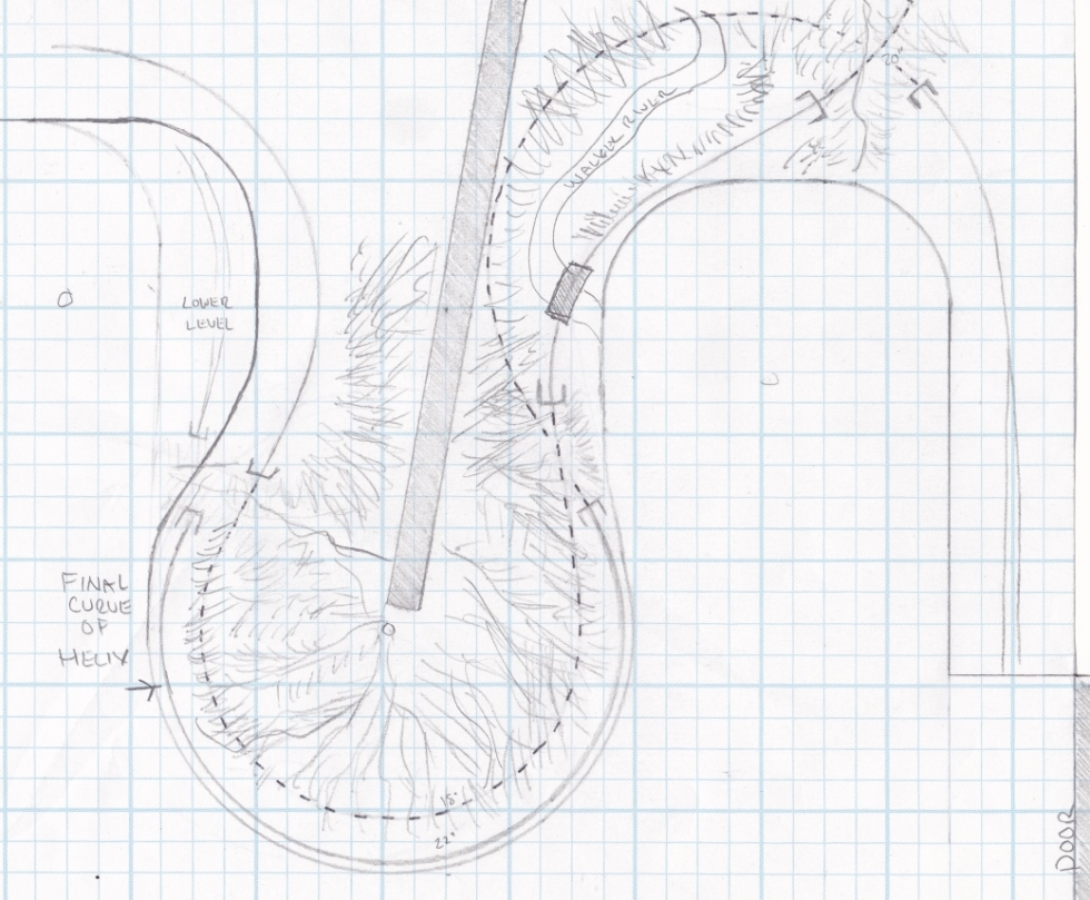
Drawing it out from a straight down view looked pretty good. Curves are within my set parameters, clearances worked out as well, and I could put in some rock wall/retaining wall scenery between the outter most helix curve and the new inner curve.
But how would the scenery look in 3D? Could I make it work?
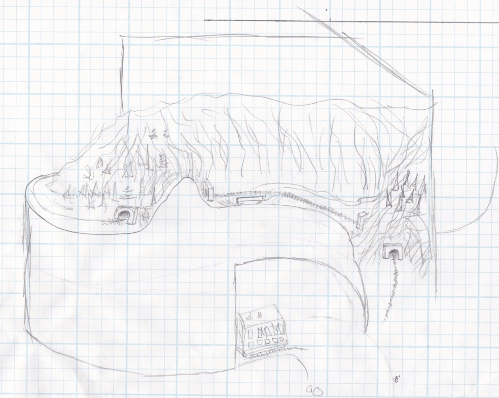
I sketched it out and it seemed to look pretty good. The negative is that the track coming around the top of the helix (left) and the track crossing the bridge (middle) are supposed to be miles apart. And those back to back tunnels on the right? Same thing, miles apart. Now, the mountain scenery is pretty much the same at both of the locations, but I would have a hard time telling visitors that the scenes they are looking at are not meant to be next to each other. I could have put in a view dividing backdrop between both those back-to-back tunnel locations, but the added construction and space they would take up wasn't worth the effort.
But pressed on I did. And no matter how I tried, I just couldn't get those "S" curves to work out properly. It was either too sharp a radius, or it hung out over the isle too far or I couldn't get a long enough straight section in between all the curves. Like I said last time, what looks good on paper doesn't always turn out good in real life!
So now I was back to asking myself what to do with that upper level main. Turning it and having it go through the backdrop kept popping up in my mind more and more, so I got out the tape and measured the distance from the hole in the wall to the other side of the backdrop. 6ft. Well, on the last layout, the lower level track was hidden from staging until it popped out at the drop down bridge. And how far was that? 5.5ft. So in essence I really wasn't losing much visible trackage if I made that upper level main hidden. At least I would have the last curve of the helix visible.
So that is what I'm doing. And I think it's going to work out pretty good! I have already put down some spline roadbed for both the main and the new June Lake siding. Ok, enough typing, lets get some pictures going. . .
.JPG)
New subroadbed added to the end of the helix. Note the spline already starting.
.JPG)
#10 and #7 turnouts. The #7 will run a siding over to the inside of the helix where a gravel plant will be.
.JPG)
New cut in the backdrop where the upper level main will pass through at.
.JPG)
Overall shot. The siding and main are split apart at left and will be molded after the twin tunnels at Kyune.
.JPG)
More spline going above the room entrance. The riser in the rear with the bent screw sticking out will support the upper level main coming out from the hole in the wall.
.JPG)
Gotta add more supports so I can continue that spline roadbed!
.JPG)
supports added in front of the window.
.JPG)
Needed more room light, so up went the fluorescents.
.JPG)
more light, more supports.
.JPG)
This area is now South Bishop (pending a look on the map for a different name) and is where most switching will be located.
.JPG)
First piece of subroadbed on the lower level!
.JPG)
Entire South Bishop below, June Lake siding above.
.JPG)
Size comparison. Autorack and 30" flex track.
.JPG)
Adding the front runners to both levels. Note the clamp on the bottom level. I had a bunch of left over pieces that were about 1/2" shorter than the 18" I was going to use for the yard. Rather than waste wood, I used those left over pieces, hence the bump out in the benchwork.
.JPG)
Because I had to drop the helix down one full turn to clear the upper level main, I had to get that last 3" back so the bench work is stepped from the helix all the way to the door entrance at a nice steady 2% grade.
.JPG)
Overview of the room as of 12/11/11
All material on The Owens Valley Subdivision website is Copyright 2007-2011 by Michael Stoner. None of the material (including text and photographs) on this web site may be reproduced in any form without prior written permission.