Taken from a thread I wrote on Trainboard.com. That thread is located here.
Lately there has been quite a bit of talk about the LifeLike/Walthers Proto GP38-2's, specifically how they are not decoder ready. I was a bit upset at this also, but after taking one apart and checking it out, it's not really that hard of an install to do. I'll take you through an install step by step.
Due to the design of the motor contacts, a Plug N Play won't work in the traditional sense, where you pop the shell, remove the stock light board, and replace it with an aftermarket decoder. For this install, we will be using a decoder that will need to be hard wired in. We will also use the stock light board, with some trace cutting involved.
I highly suggest that this NOT be your first time trying to hardwire a decoder in, since this install is a bit more involved than a late style Atlas loco.
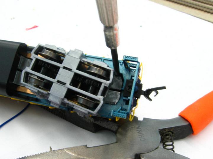
Shell removal:
When you first try to take the shell off, you'd think that they glued it on! But using a small flathead screwdriver, it'll come right off.
Take and insert the screwdriver behind the rear trucks between the frame and shell and gently pry up on the shell, working it back and fourth. You might also have to jump from side to side. Eventually the shell will start to come up. After a certain point, the shell will slide off.
Note: you can take and file down the 4 small nubs on the frame to make the shell easier to get on and off for future maintenance.
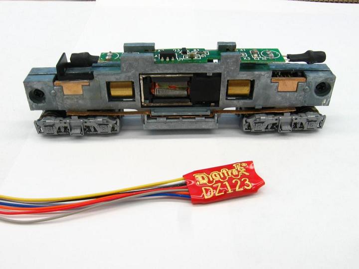
For this install, I'll be using a Digitrax DZ123. It is an older decoder, but it is what I had available. Most of the new decoders out now are smaller than this, but there is plenty of room in the rear under the light board, so this one will fit just fine.
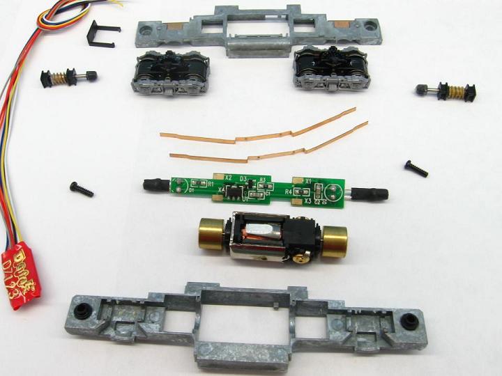
After taking the frame apart, but before you take the motor out, make sure you mark on the motor which side is up. I did this using an Xacto blade.
Here is the loco disassembled.
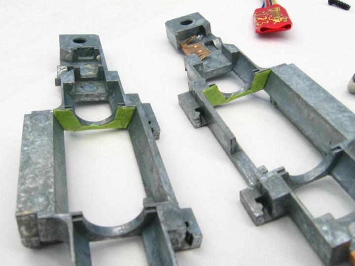
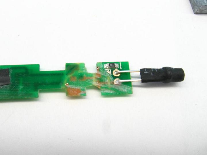
One thing that was noted was how close the front of the motor is to the frame. I was able to push the motor forward and backward in the frame and it seemed to touch it, which would cause a short and fry the decoder. I had read that this happened to someone, so we won't take any chances, we'll insulate it.
I covered the recessed area to the front of the motor using some thin tape. It doesn't have to follow the frame perfectly, but get it as close as you can. You can use whatever you want, as long as it is very thin and will stay in position. Once this is done, check to see if the motor goes back in. A snug fit is ok, but if you have to really push hard, then the tape is too thick.
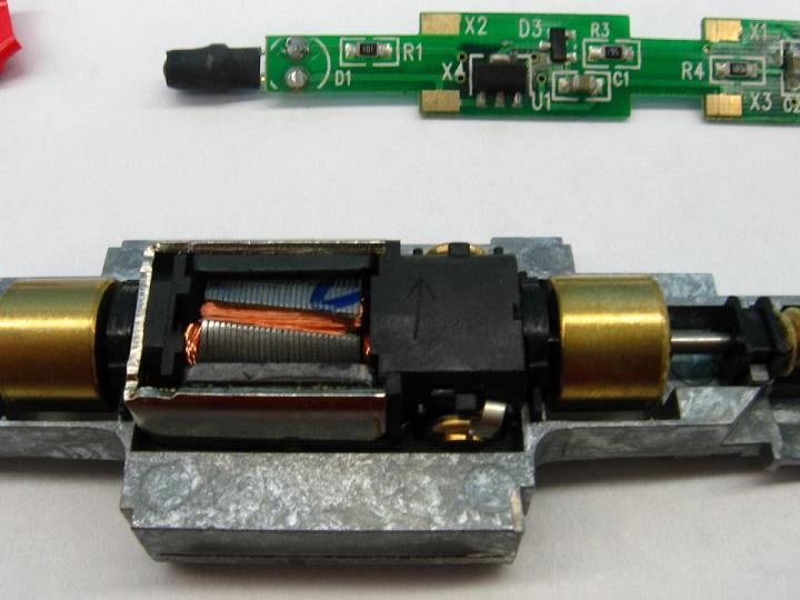
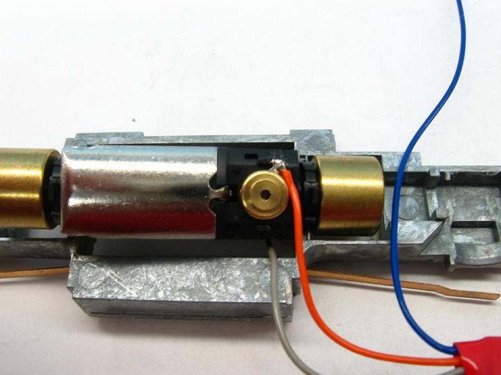
On to the motor, and we'll take and unfold those small contact strips and cut them almost all the way off. You'll want to leave a little sticking out for a place to solder the wire to.
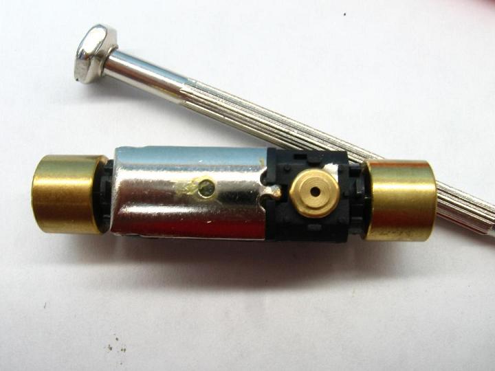
While checking the fit of the motor, you can take a file or cut off disk and make a small groove in the motor for the wire to sit in. It doesn't have to be very deep, just enough for the wire to want to lay in. You can see it to the right of the arrow.
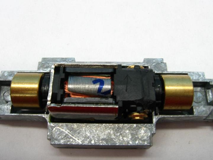
Now we will take and solder the 2 motor wires on. Try to use a minimal amount of solder. This area is close to the frame, but is not touching. If you think you got too much on and it might touch, then use some tape over the exposed area.
Note the wire laying in the recessed area on the motor.
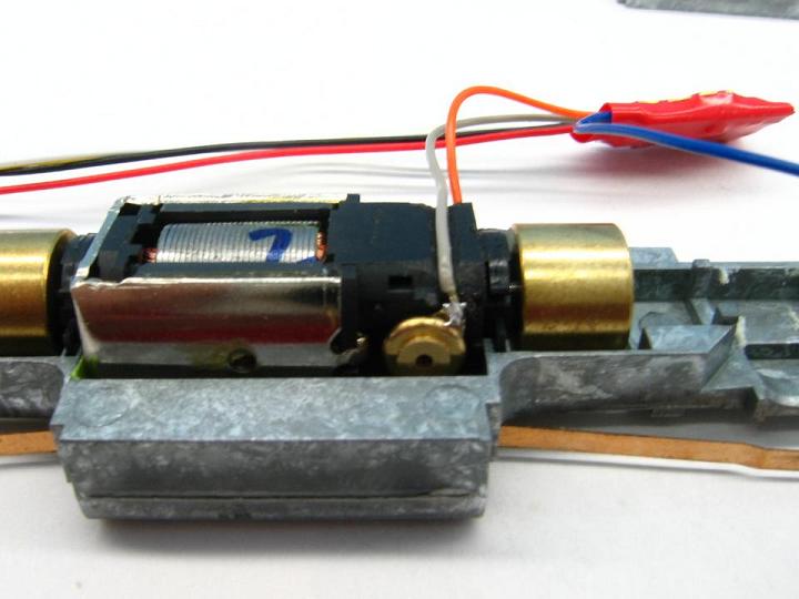
Do the same thing with the Orange wire, but make sure to run it towards the Grey wire, since it will come up through the frame and light board on the far side.
Next thing in line is the stock light board. There is a bunch of stuff on here that we won't be using. All we will use is the 2 resistors that have the small "195" on them. Here is all the places where the traces need to be cut. The shaded area on the rear will need to be completely cut out for wire access.
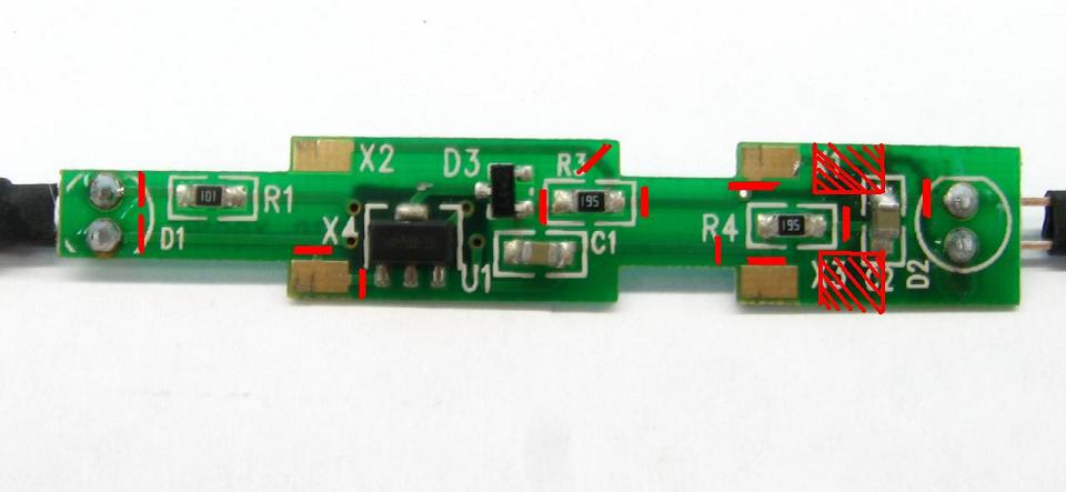
As you have noticed, there is a bunch of stuff on the bottom of the light board at the rear. This will all need to be cut off for the decoder to fit. Don't bother trying to unsolder any of it, file it off or use a cut off disk to take it off. Make sure you don't leave any bare traces showing! Sand it down completely. I left the small resistor on just in case I needed it, but it can also be removed if you choose so.
With the loco back together, it's time to set the decoder in place and work on soldering the wires to the light board.
Here is where those large cutout areas on the light board come in to play. Set the decoder under the rear LED and pass the wires up through those cutouts to the top. I put the Orange, Grey and Blue on one side, and the Yellow, White, Red and Black on the other.
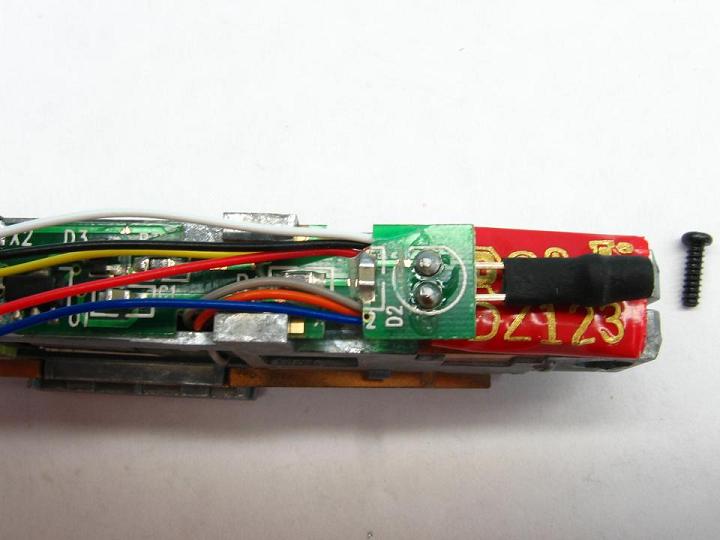
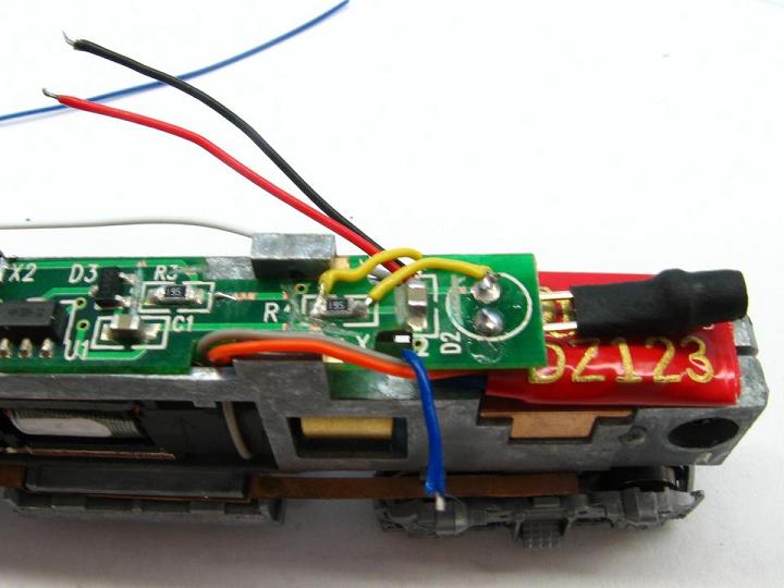
The first wire to start with will be the rear headlight wire, which is the yellow one. This wire will go from the decoder to the left side of the rear "195" resistor, then from the other side of the resistor to the top LED lead.
At this time, you can also cut and tin the Red and Black pickup wires, but do not solder them in.
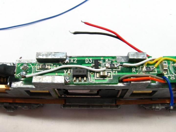
Next up is the front headlight wire, which is the white one. This wire will go from the decoder to the right side of the front "195" resistor, then from the other side to the lower LED lead.
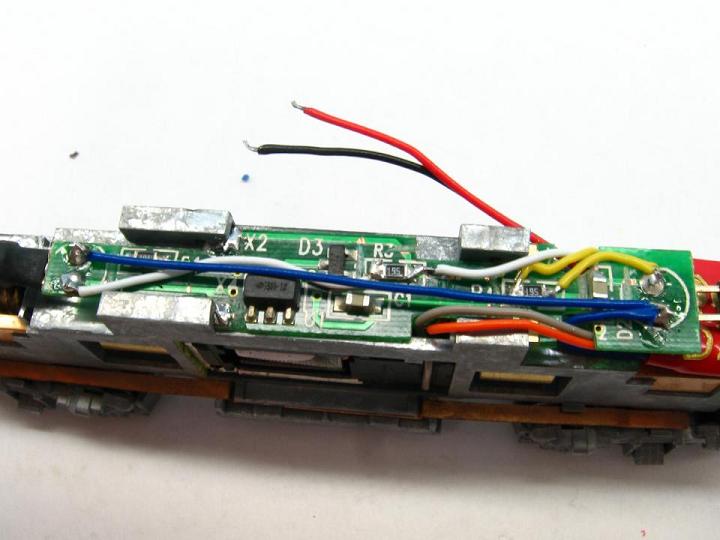
Now we'll take the Blue common wire and run it from the decoder to the rear LED. From there, we'll run another Blue wire up to the front LED.
Once those wires are soldered in, we can add the last 2 wires, the Red and Black pickup wires. You might have noticed that the cutting of the traces has now isolated each front and rear side pad from each other. I have found that using only the front 2 pads still allows the loco run smooth with no hesitation due to how tight the light board is against the frame. If you feel that it is not tight enough, then by all means, go ahead and add some jumper wires from the front pads to the rear pads. Another option is to add some solder to the entire front pad to make it tighter.
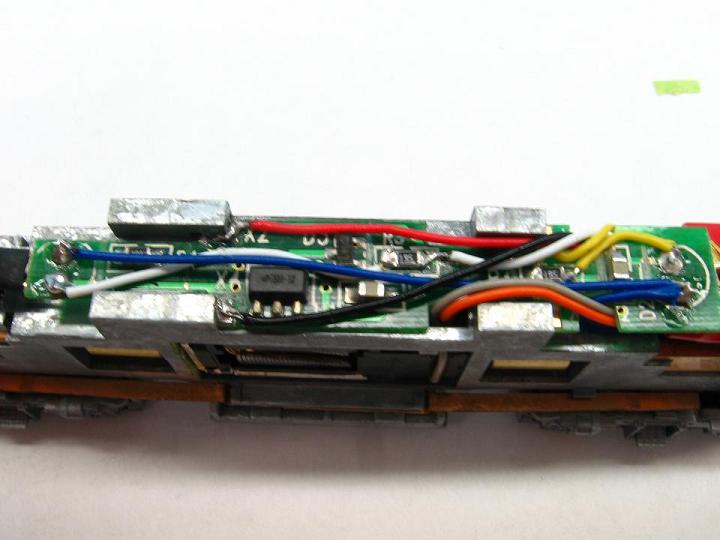
Do what you feel comfortable with. After running this loco for almost a year with just the front pads as pickup, I have yet to have any sort of contact problems.
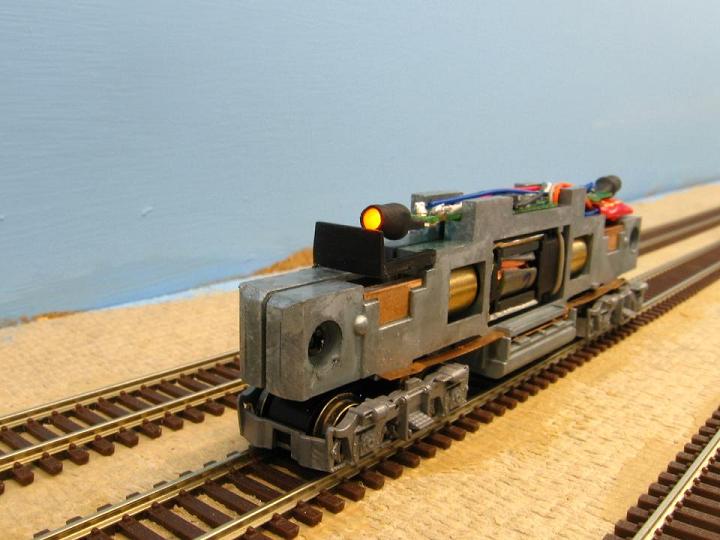
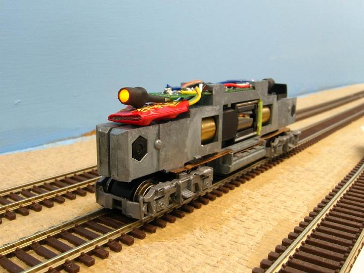
After these wires are installed, put the loco on the test track and program it to your liking. Here is the finished loco, front and rear.
All material on The Owens Valley Subdivision website is Copyright 2007-2009 by Michael Stoner. None of the material (including text and photographs) on this web site may be reproduced in any form without prior written permission.