April 7th, 2009
Not much visually done in the last week. I've had some other things come up non train related, and I helped my friend Chris out in designing his new layout. He goes by "Hutch" on Trainboard. He has a nice sized room but wasn't using it to it's full potential. So after a few emails with him, I drew up a nice sized double deck layout that he really liked. In fact, he's already started on it. You can follow his blog by going here: http://appalachiansouthern.com/
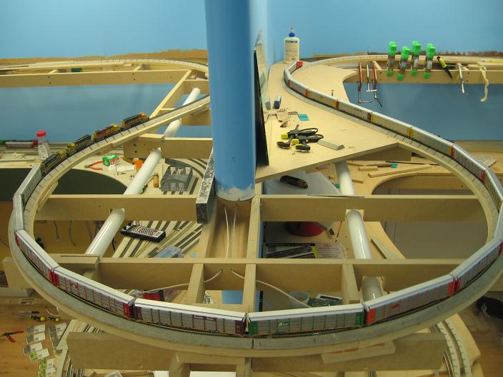
Most of what I've done this last week has been wiring. I was getting sick of having jumper wires going from the lower level to the upper level to test out the track and run trains. So I ended up wiring in the main line at the June Lake siding. Wiring is a pain when you have to account for train detection. I also got in the habbit of attaching feeder wires to every piece of track, no matter how small it is. No more relying on rail jointers for current.
The other issue that came up with my wiring ventrue is my solder connections. I've been having problems on the lower level with my solder joints coming loose. Not good when you wanna run trains! So I've devised a new way to solder the wires to the rails. Granted, my soldering skills are pretty lacking, but the way I was doing it was not working, and it made alot of mess on the rails with huge oversized globs of solder. So outlined below is my new way to solder the feeders to the rails. I hope this way will work better than what I was doing. It makes the feeders less obvious, that's for sure!
I take a piece of flex track and pop loose 2 ties from it where I want to put my feeder wires at before I glue it down.
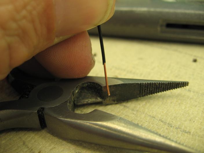
I use 22 awg telephone wire for my feeders. First I'll take and squish about 1/8" in the pliers.
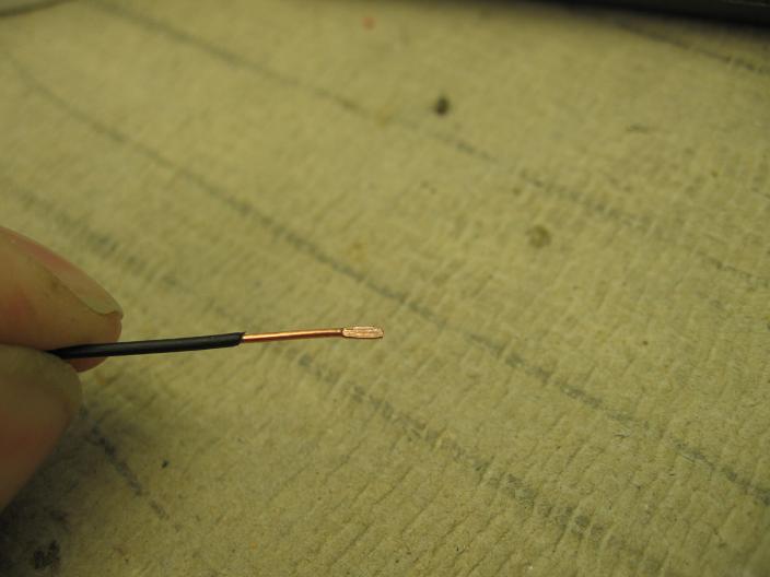
Here is the end squished down flat.
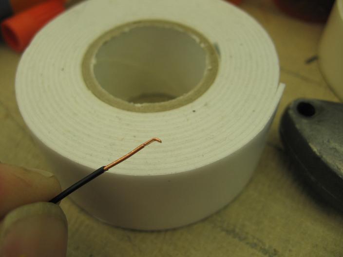
Then I give it a bend. Not a full 90 degree, but more like a 60 degree bend. That way it will lay on the bottom web of the rail when in place.
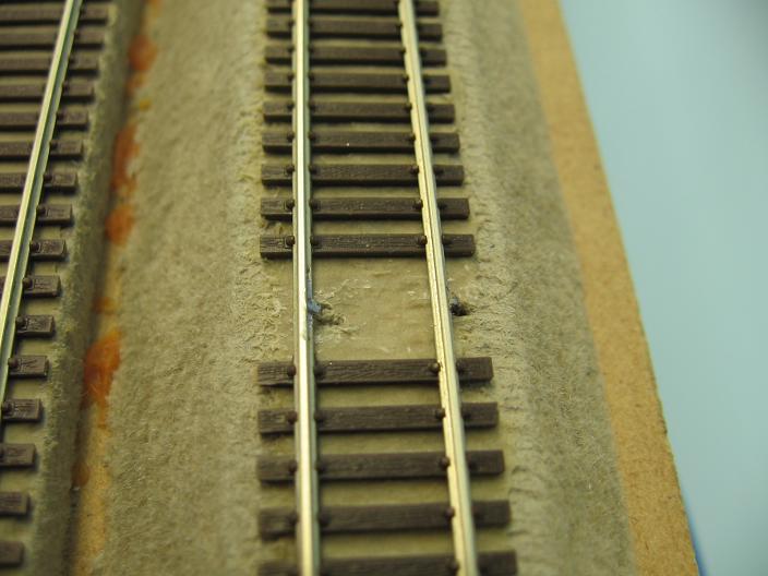
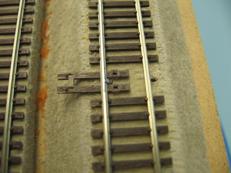
I then tin the wire and the rail, slide it down through the hole in the roadbed and solder it in place. I also make sure to put both feeders on the backdrop side of the track so you don't see them when looking at the track. Once last thing - I make sure the holes are centered between the ties...
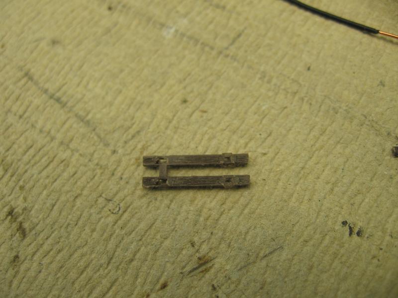
...because when I slip the tie strip back into place, I want the feeder wires to go between these ties and still keep them in alignment with the rest of the ties. Note that I cut out the plastic connector between one side of ties and left the molded on spikes on the side opposite the backdrop.
I cut it out so the tie strip will slide back into place and miss the feeders. I leave the plastic part between the other side so it will hide the feeder wire when in place and looking at it from that side.
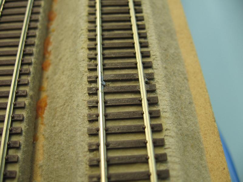
Here is the tie strip back in place snuggled in between the feeder wires.
The only tell tale sign that there are feeders there is the missing plastic spikes on the far side of the ties.
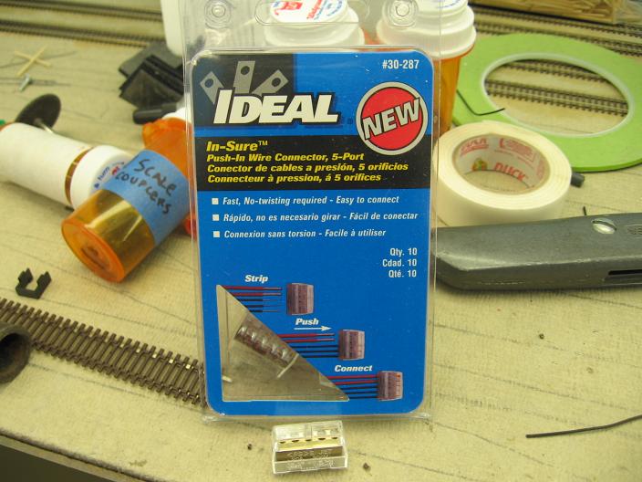
I came across these connectors at Home Depot. They come in 2,3,4 and 5 hole styles. They fit wire sizes from 14-22 awg. There are 10 in a pack. The 5 hole style costs $2.00 and will give you 50 connections.
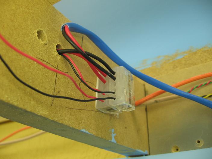
Here they are implemented on the layout. It takes 2 of them for a connection. With this one, I have the buss line coming in and going out, plus 2 feeder wires going out. I'll be adding another set of feeders in the last 2 holes.
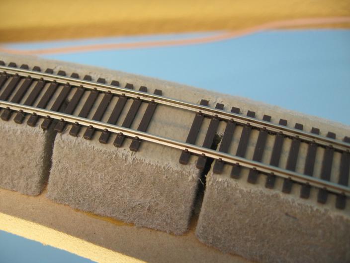
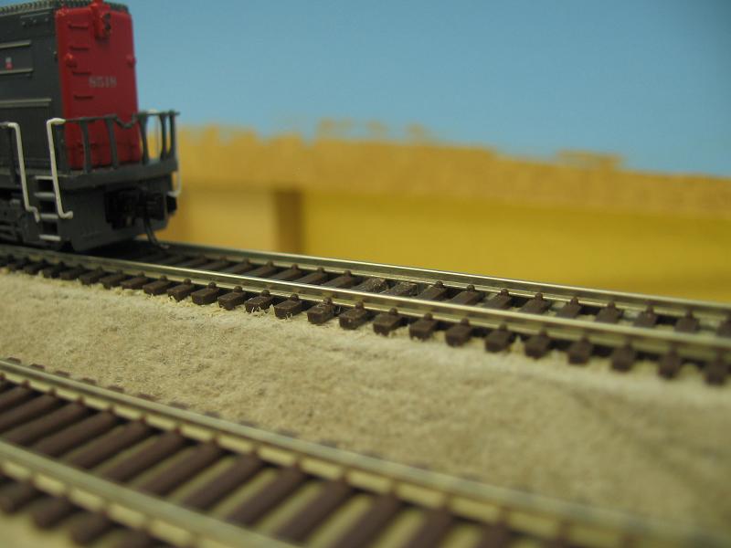
How about a train pic? I've glued the track down to where the caboose is on the right hand side. This is a 22" radius curve. The town of Bridgeport will be on the right side...eventually.
All material on The Owens Valley Subdivision website is Copyright 2007-2010 by Michael Stoner. None of the material (including text and photographs) on this web site may be reproduced in any form without prior written permission.